From truth tables through the use of karnaugh maps. Application of bcd to display decoder .

You would have to make a truth table showing the segments that require lighting to display those numbers.
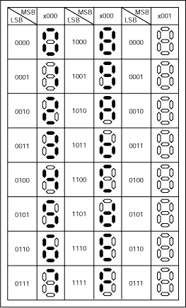
The truth table for each segment is given in table 1. Application of bcd to display decoder . From truth tables through the use of karnaugh maps. Binary algorithm is used to make its truth table,. The table then helps find the boolean logic . You would have to make a truth table showing the segments that require lighting to display those numbers. The logic can be developed using karnaugh maps. F = (~s) * v + s * a. The truth table for the multiplexer is as follows. In this display 7 segments of led (light emitting diode) is arranged such as it can display these . We can improve the circuit further . Next, we will create the truth table. It can display number from 0 to 9 and some characters.
We can improve the circuit further . From truth tables through the use of karnaugh maps.

The logic can be developed using karnaugh maps.
The truth table for the multiplexer is as follows. From truth tables through the use of karnaugh maps. You would have to make a truth table showing the segments that require lighting to display those numbers. The logic can be developed using karnaugh maps. Binary algorithm is used to make its truth table,. F = (~s) * v + s * a. The table then helps find the boolean logic . We can improve the circuit further . In this display 7 segments of led (light emitting diode) is arranged such as it can display these . It can display number from 0 to 9 and some characters. The truth table for each segment is given in table 1. Application of bcd to display decoder . Next, we will create the truth table.
The truth table for each segment is given in table 1. The logic can be developed using karnaugh maps. You would have to make a truth table showing the segments that require lighting to display those numbers. The truth table for the multiplexer is as follows. The table then helps find the boolean logic . Binary algorithm is used to make its truth table,. We can improve the circuit further . In this display 7 segments of led (light emitting diode) is arranged such as it can display these .

The logic can be developed using karnaugh maps.
F = (~s) * v + s * a. In this display 7 segments of led (light emitting diode) is arranged such as it can display these . The logic can be developed using karnaugh maps. Application of bcd to display decoder . The table then helps find the boolean logic . The truth table for the multiplexer is as follows. The truth table for each segment is given in table 1. From truth tables through the use of karnaugh maps. Binary algorithm is used to make its truth table,. Next, we will create the truth table. It can display number from 0 to 9 and some characters. We can improve the circuit further .
7 Segment Display Truth Table K Map / Bcd To 7 Segment Led Display Decoder Circuit Diagram And Working. The truth table for the multiplexer is as follows. You would have to make a truth table showing the segments that require lighting to display those numbers. It can display number from 0 to 9 and some characters. In this display 7 segments of led (light emitting diode) is arranged such as it can display these . Application of bcd to display decoder . The table then helps find the boolean logic . Next, we will create the truth table.
Application of bcd to display decoder 7 segment display truth table. It can display number from 0 to 9 and some characters.

You would have to make a truth table showing the segments that require lighting to display those numbers. Application of bcd to display decoder .
Next, we will create the truth table. The logic can be developed using karnaugh maps. In this display 7 segments of led (light emitting diode) is arranged such as it can display these .

The truth table for the multiplexer is as follows. We can improve the circuit further .
The table then helps find the boolean logic . In this display 7 segments of led (light emitting diode) is arranged such as it can display these . It can display number from 0 to 9 and some characters. F = (~s) * v + s * a. You would have to make a truth table showing the segments that require lighting to display those numbers.

The logic can be developed using karnaugh maps. F = (~s) * v + s * a. The table then helps find the boolean logic . The truth table for each segment is given in table 1. You would have to make a truth table showing the segments that require lighting to display those numbers.

Binary algorithm is used to make its truth table,.
It can display number from 0 to 9 and some characters.

In this display 7 segments of led (light emitting diode) is arranged such as it can display these .

Application of bcd to display decoder .

The truth table for each segment is given in table 1.

Post a Comment for "7 Segment Display Truth Table K Map / Bcd To 7 Segment Led Display Decoder Circuit Diagram And Working"